Normals Explained: From Surface Math to Normal Maps
If you've spent any time in a material editor, you've seen it: that blue-purple texture plugged into the Normal input. Someone told you it adds surface detail, and it does — but that explanation doesn't really tell you what's happening.
Normal vectors are at the core of how real-time rendering works. They decide how light hits a surface, whether a face gets drawn at all, how physics objects bounce, and how reflections orient themselves. The normal map is just one application of that — a way to supply per-pixel normals that the geometry can't afford to provide.
This article starts from the math and builds up: what a normal actually is, where it gets used, and what a normal map is really storing under that blue.
What Is a Normal Vector?
A normal vector is a vector that points perpendicular to a surface at a given point. More precisely, it's perpendicular to the tangent plane — the flat plane that just touches the surface at that point without cutting through it.
In practice, normals are always unit vectors: their length is exactly 1. This matters because most operations that use normals — dot products, reflections, transformations — only work correctly if the vector is normalised. Unnormalised normals produce incorrect lighting, and it's a surprisingly common source of subtle artefacts when normals are interpolated or transformed without renormalisation.
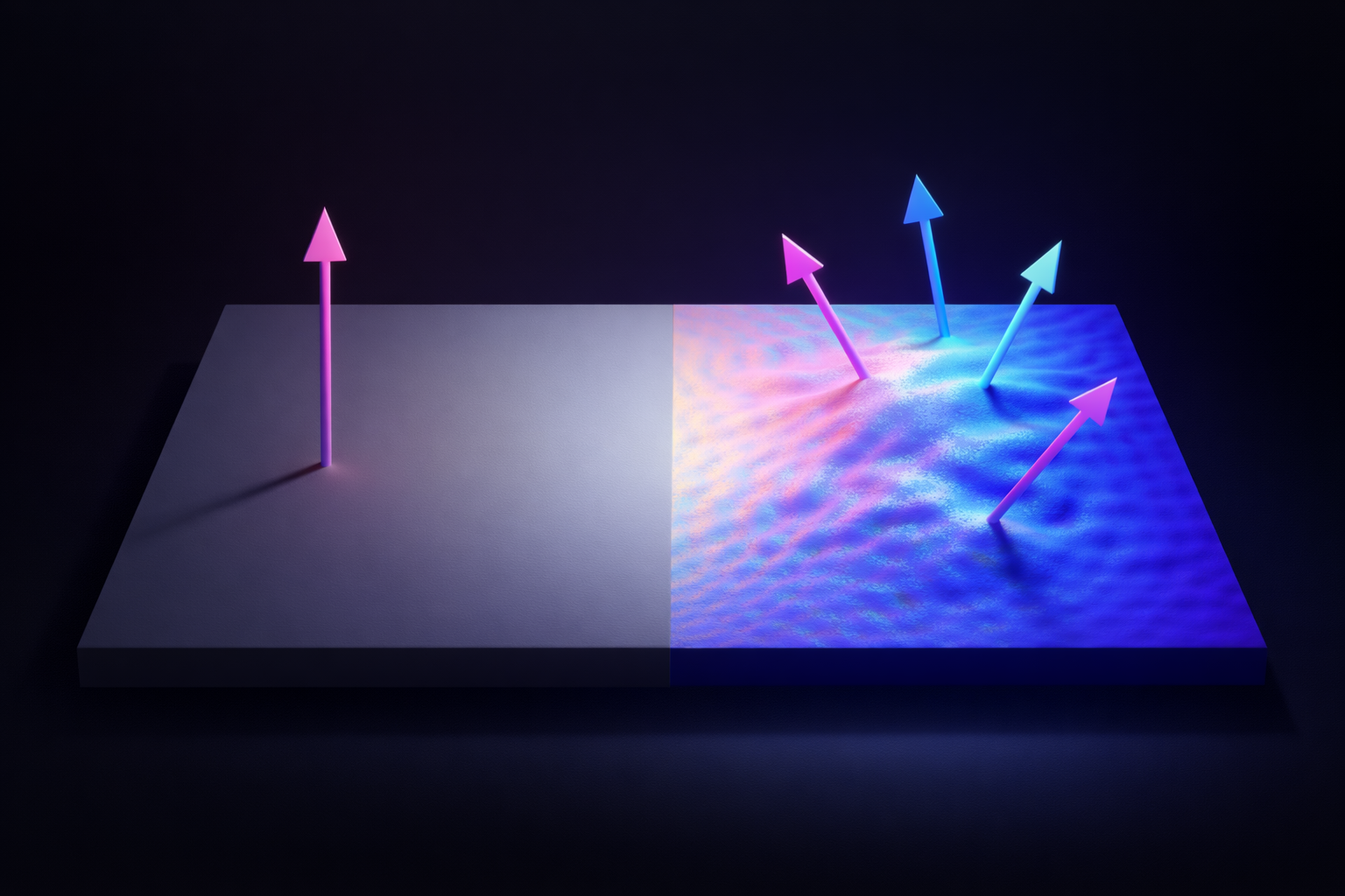
On a flat polygon, the face normal points uniformly away from the surface. On a curved surface, it changes direction continuously as you move across it, always staying perpendicular to the local tangent plane.
Normals and Lighting — The Dot Product
The most important job a normal has is driving lighting calculations. The core operation is the dot product, and it's worth understanding properly.
Bear with me for one paragraph — once this clicks, you'll understand every lighting calculation in every engine you'll ever use.
The dot product of two unit vectors gives the cosine of the angle between them — a value between -1 and 1. Applied to lighting, if you take the dot product of the surface normal N and the direction to the light source L, you get a scalar that tells you how directly the surface is facing the light:
- dot(N, L) = 1.0 → surface points directly at the light — full brightness
- dot(N, L) = 0.0 → surface is perpendicular to the light — grazing angle, no contribution
- dot(N, L) < 0 → surface faces away from the light — in shadow, clamped to zero
This is Lambertian diffuse lighting — the foundational model for matte surfaces. It's cheap to compute, physically plausible for rough surfaces, and the reason a sphere lit from the left gets brighter on the left and falls off toward the right.
Specular lighting uses the normal differently. The light direction is reflected around the surface normal to get a reflected vector R, and that's compared against the view direction V. When R and V align, you're looking directly at the specular highlight. The roughness of the surface controls how tight that comparison is.
In PBR, the normal participates in BRDF evaluation at every pixel — it's one of the most frequently sampled values in the lighting pass. Getting it right, and getting it right per-pixel, matters.
Beyond Lighting: Other Uses of Normals
Lighting gets all the attention, but normals are doing useful work in several other places that are easy to miss.
Backface Culling
Every closed mesh has a front face that should be visible and a back face that shouldn't. The GPU figures out which is which using the face normal and the view direction.
If the dot product of the face normal and the direction to the camera is negative, the face is pointing away. It's a back face — the GPU discards it entirely before rasterisation, and no pixel shader ever runs for it.
It's one of the cheapest culling techniques available, and it only works because the normal tells the engine which way the surface is facing.
Collision and Physics Response
When a physics object hits a surface, the engine needs to know two things: that a collision occurred, and what direction to push the object in response. The second answer is the collision normal — the surface normal at the point of contact.
The reflected velocity is computed exactly the same way as a specular reflection: the velocity vector is mirrored around the collision normal. A ball hitting a flat wall bounces straight back; a ball hitting a surface at an angle reflects at the corresponding outgoing angle. Without the normal, none of that is directionally correct.
Note that collision normals come from physics collision geometry, not from the render mesh or its normal map. Normal maps have no effect on physics — they only exist in the rendering pipeline.
Reflections and Environment Sampling
Cubemap reflections and screen-space reflections both rely on the surface normal. The view direction is reflected around the normal to produce a reflection vector, and that vector is used to sample an environment map or trace back into the screen buffer.
Because this reflection depends on the per-pixel normal, a normal map can directly affect how reflections look on a surface. A flat mirror reflects the environment cleanly; a surface whose normal map describes scratches and micro-bumps produces a subtly distorted, more realistic reflection.
Line Traces in Unreal Engine
If you've ever done a line trace in Unreal Engine, you've already used normals in gameplay code. The FHitResult struct returned by the trace includes an ImpactNormal field — the surface normal at the exact point of contact, in world space.
It shows up constantly in gameplay systems:
- Decal and effect alignment — spawning a bullet impact decal oriented flush with the hit surface by rotating it to face
ImpactNormal - Slope detection — checking whether a surface is too steep to stand on by comparing
ImpactNormal.Zagainst a threshold - Projectile deflection — reflecting the projectile velocity around
ImpactNormalfor ricochet behaviour - Surface-aligned placement — snapping an object flush against any surface at the hit location
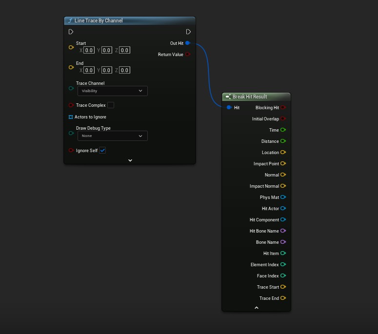
ImpactNormal is one of the output pins on the hit result.
One important caveat: ImpactNormal comes from the physics collision geometry, not the render mesh. Normal maps have no effect on it. The same separation between rendering and physics that applies to collision response applies here too.
The Low-Poly Problem: Vertex Normals and Smooth Shading
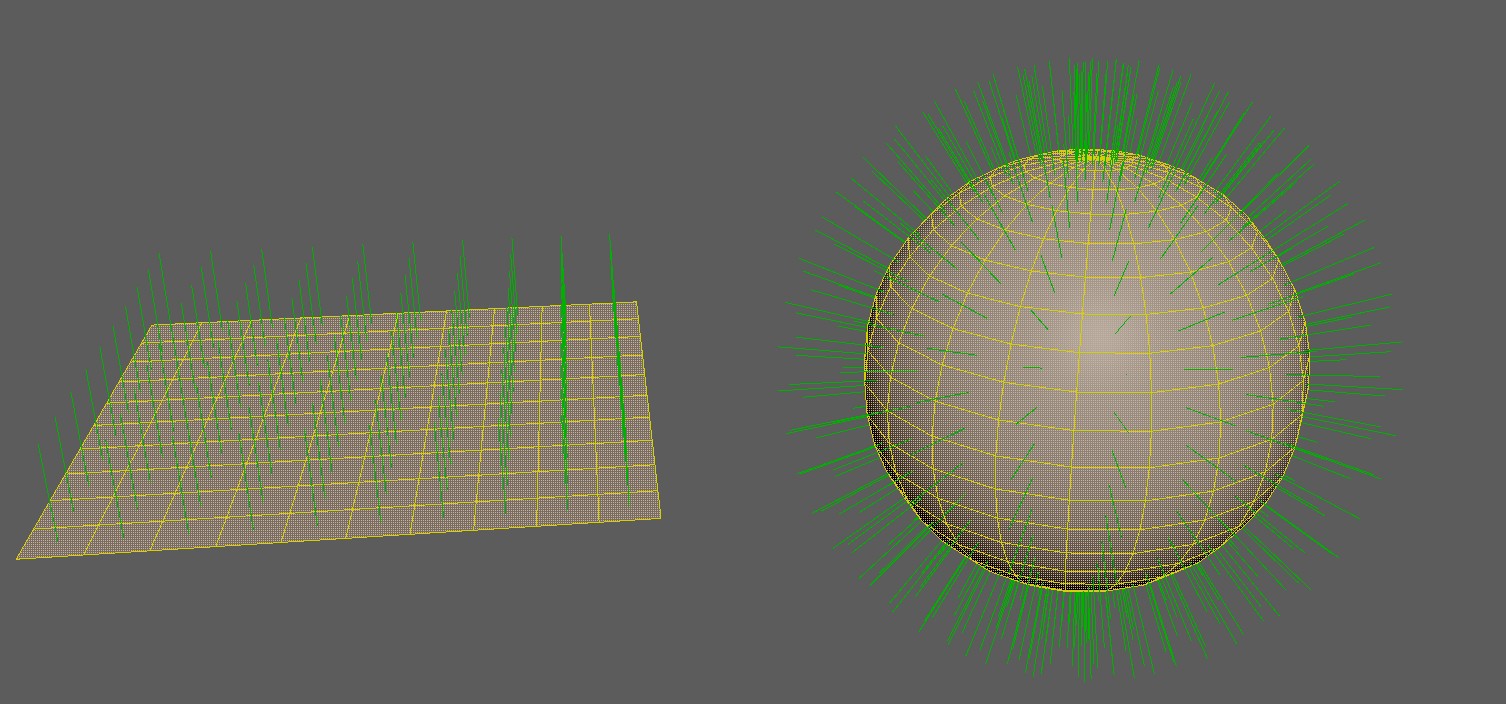
Every polygon in a mesh has a geometric normal: the direction perpendicular to that flat face. If the renderer uses face normals directly, lighting evaluates the same value across the entire polygon. Adjacent faces each have their own discrete normal, so the boundary between them produces a hard shading break. This is flat shading, and on a low-poly sphere it makes every face visible.
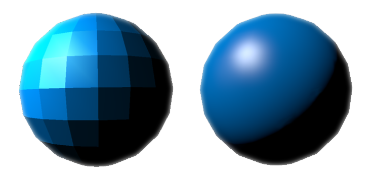
The standard fix is vertex normals. Instead of one normal per face, each vertex stores a normal that is the weighted average of the face normals of all polygons that share that vertex. The renderer then interpolates the vertex normals across the face during rasterisation — a process called Gouraud shading at the per-vertex level, or simply smooth shading in practice.
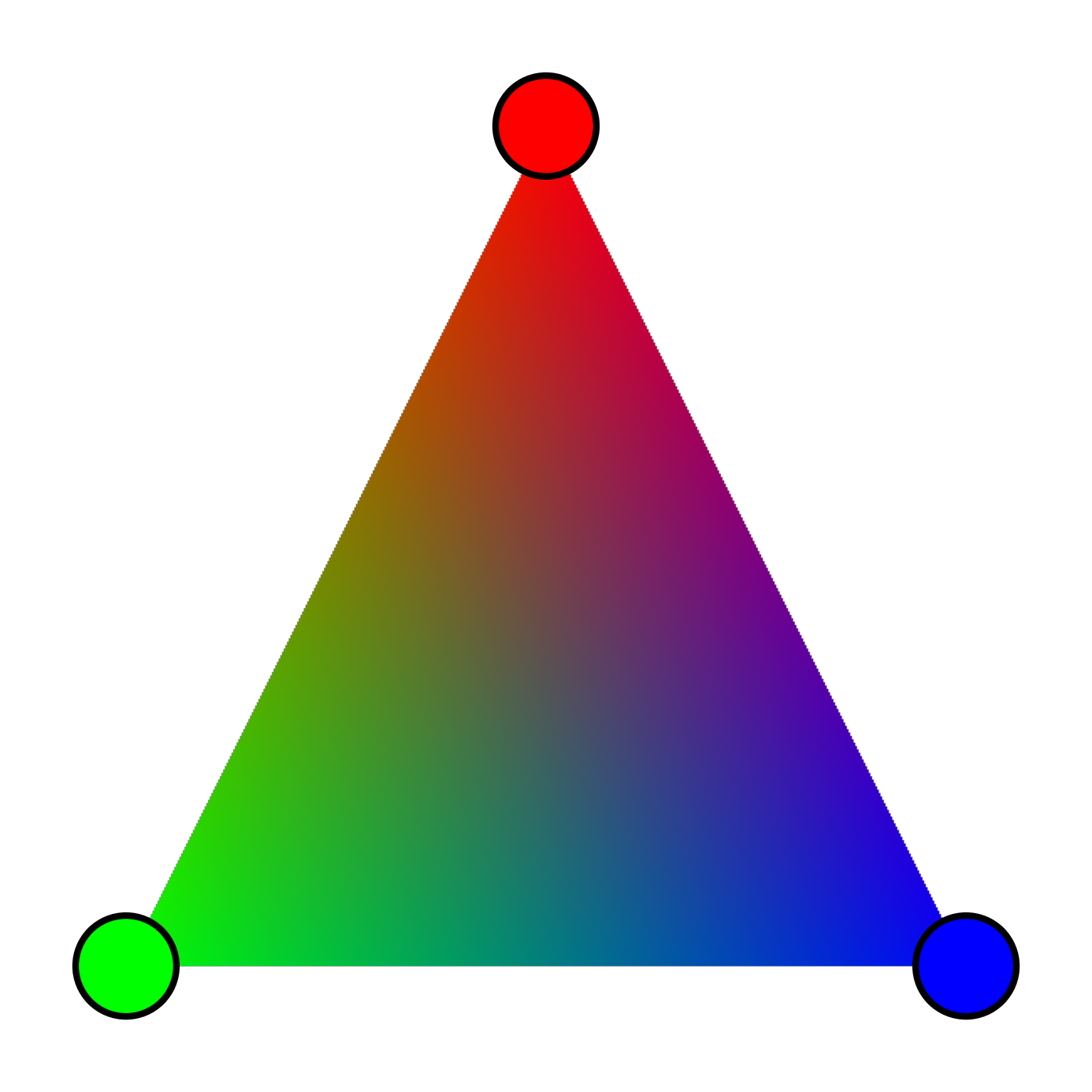
Think of it like colour interpolation across a triangle: a renderer can blend smoothly between a red vertex, a green vertex, and a blue vertex — producing a continuous gradient with no hard edges. Normal interpolation works the same way. Each pixel's normal is a weighted blend of the vertex normals at the triangle's corners, based on where that pixel sits within the face.
With smooth normals, the lighting varies continuously across the surface, and the low-poly silhouette becomes much less obvious in well-lit scenes. But smooth normals are still based on the geometry. They can fake a smooth curve, but they can't fake a rivet, a seam, a scratch, or any surface detail that isn't reflected in the actual polygon count.
That's the problem normal maps are designed to solve.
Baking: Projecting High-Poly Detail onto Low-Poly
So where does a normal map actually come from? The answer is a bake — and understanding the process makes it a lot clearer what the texture is really doing.
The standard production workflow is to build two versions of a mesh: a high-poly with all the surface detail — bolts, scratches, panel seams, fabric weave — sculpted or modelled in full, and a low-poly optimised for real-time use with a fraction of the triangle count. The high-poly never ships in the game. It exists solely as the source of truth for the bake.
During baking, the tool (Marmoset Toolbag, Substance Painter, Blender, or a dedicated baker) casts rays outward from the surface of the low-poly mesh. Each ray travels toward the high-poly and records the surface normal at the point of intersection. That normal is then stored into the corresponding texel of the normal map, transformed into the low-poly's tangent space.
The result is a texture that encodes, per pixel, what direction the surface would be facing if it had all the detail of the high-poly. At runtime, the low-poly uses that stored direction for lighting instead of its own interpolated vertex normal — and the GPU has no idea how few polygons are actually there.
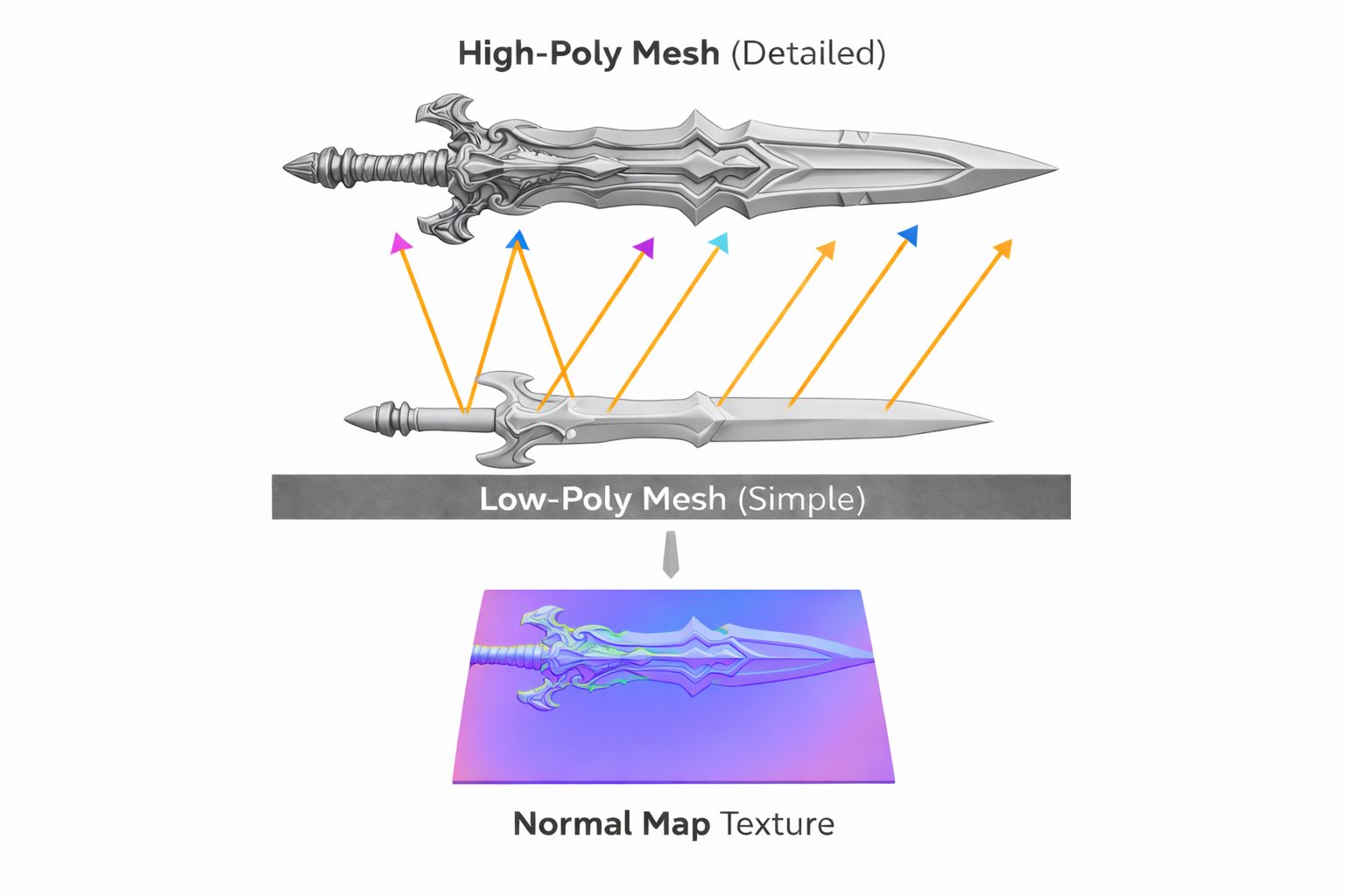
One common baking artefact comes from ray distance. If the high-poly and low-poly diverge too much in shape, rays can miss, overshoot, or hit the wrong surface. Most bakers address this with a cage — a slightly inflated copy of the low-poly that defines exactly where each ray starts, ensuring consistent coverage and avoiding self-intersection errors. Getting the cage right is one of the more tedious parts of a clean bake.
What's Actually Inside That Blue Texture
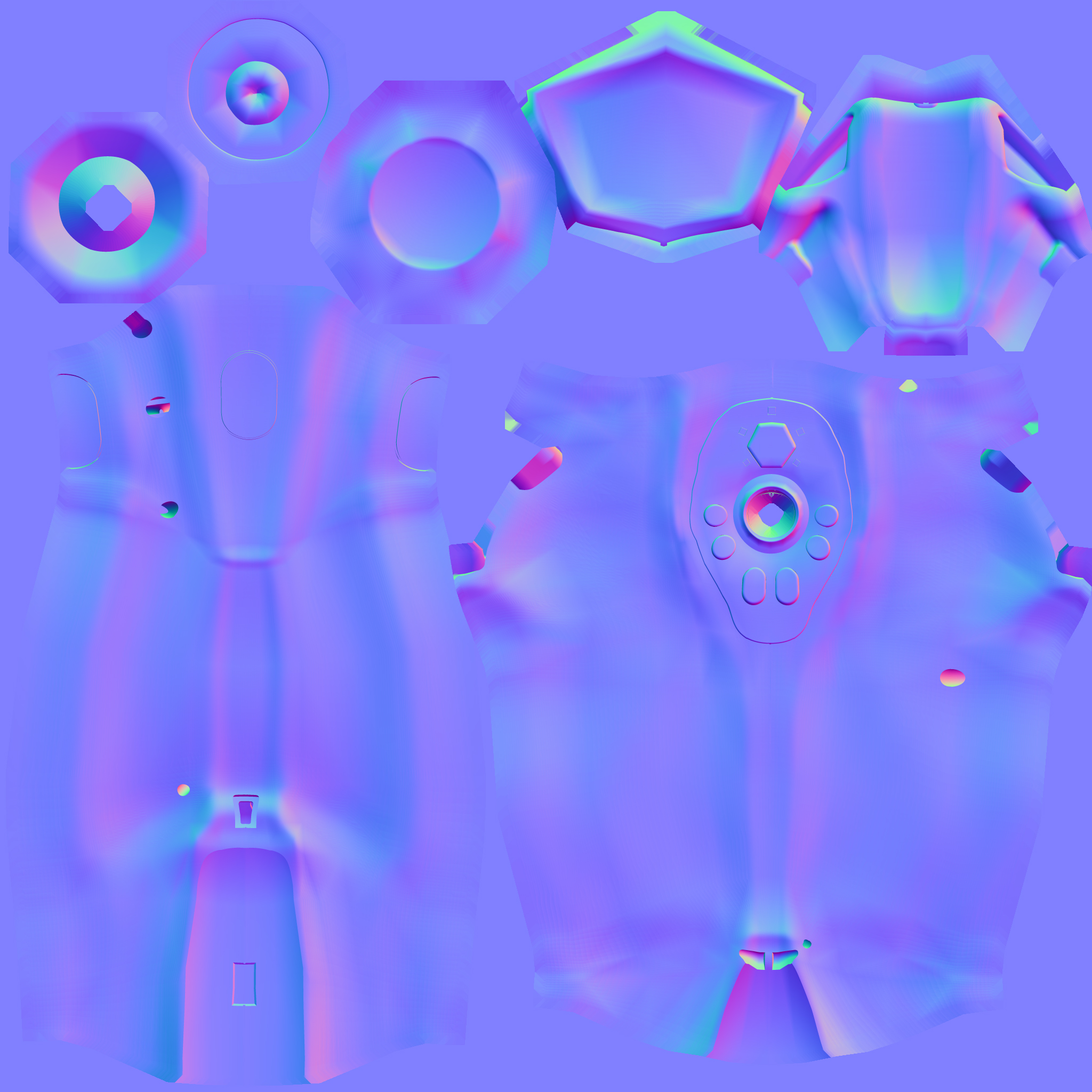
RGB(128, 128, 255) — a flat surface pointing straight up. Colour shifts encode tilted normals.A normal map is a texture where each pixel encodes a direction vector instead of a colour. That direction represents the surface normal at that point, as if the surface had the detail of a much higher-resolution mesh.
Direction vectors have three components (X, Y, Z), and textures have three colour channels (R, G, B). The mapping is direct: X goes into the red channel, Y into green, Z into blue. Since directions range from -1 to 1 but colour values range from 0 to 1, the values are remapped: a direction component of -1 maps to 0, and +1 maps to 1. The neutral value, 0, maps to 0.5 — the mid-grey you'd see on a flat region.
At runtime, the shader reads the RGB value from the normal map, unpacks it back to the -1 to 1 range, and uses that vector in the lighting calculation instead of the interpolated vertex normal. The geometry doesn't change — only the normal that the shader sees.
This is why normal maps are effective for surface detail but don't affect silhouettes. If you look at a mesh edge-on, the normal map has no influence there — the silhouette is still determined by the actual geometry.
Tangent Space — Why the Map Looks Blue
You can store a normal direction in any coordinate space. The choice matters more than it might seem — and understanding the most common one, tangent space, is what explains why normal maps always look blue.
In tangent space, normals are stored relative to the surface itself, not to the world or to the object. Each point on a mesh has a local coordinate frame defined by three vectors:
- Tangent (T) — points along the U direction of the UV map
- Bitangent / Binormal (B) — points along the V direction of the UV map
- Normal (N) — points away from the surface, perpendicular to both
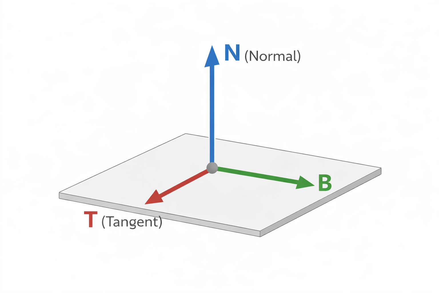
A completely flat surface has a normal that points straight along the surface's own N axis — a direction of (0, 0, 1) in tangent space. Encode that into 0–1 range: (0.5, 0.5, 1.0). In RGB values that's RGB(128, 128, 255) — medium-grey red, medium-grey green, and full blue — which is why flat regions of a tangent-space normal map appear as that distinctive blue-purple.
Any deviation from flat shifts the X or Y components. A bump tilts the normal toward a different angle, so the red and green channels shift away from 0.5. The blue Z component tends to stay high because the normal can't tilt more than 90 degrees from vertical without pointing into the surface, which would be physically wrong.
The key advantage of tangent space is portability. Because the normals are expressed relative to the surface, the same normal map can be reused on different meshes, at different orientations, and the result is always correct. It also tiles naturally along UV seams, and it works on deforming or animated meshes because the tangent frame deforms with the mesh.
Object Space and World Space Normal Maps
Tangent space is the default, but it's not the only option — and knowing the alternatives helps you understand why tangent space won.
Object space normal maps store directions relative to the object's local coordinate frame. They're straightforward to bake and easier to read visually — each face of the mesh tends to be a distinct solid colour corresponding to its orientation. They're used in some stylised workflows and for hard-surface assets where deformation isn't needed. The limitation is that the map is tied to a specific object orientation: rotating the mesh breaks the normals unless the map rotates with it. You also can't tile an object-space normal map.
World space normal maps store directions in absolute world coordinates. They're occasionally used in terrain systems or baked lighting workflows where the surface orientation is fixed and known. They're rare in general asset pipelines because they break on any object that moves or rotates.
| Space | Stored Relative To | Tileable | Works on Deforming Mesh | Typical Use |
|---|---|---|---|---|
| Tangent Space | The surface itself (UV frame) | ✓ Yes | ✓ Yes | Almost everything — the default |
| Object Space | The mesh's local axes | ✗ No | ✗ No | Hard-surface, stylised, non-deforming assets |
| World Space | Absolute world axes | ✗ No | ✗ No | Fixed terrain, baked lighting passes |
Common Gotchas (and How to Spot Them)
The DirectX / OpenGL Y-Flip
This one catches everyone at least once. It's invisible until you move a light — then suddenly the baked shadows appear on the wrong side of bumps, as if the lighting is inverted on one axis.
The cause is a disagreement about which direction Y points in UV space. DirectX defines +Y as pointing downward in texture space (toward the bottom of the image). OpenGL defines +Y as pointing upward. When a normal map baked in one convention is used in an engine that expects the other, the green channel is effectively inverted, and the Y component of every stored normal is backwards.
In Unreal Engine, the Flip Green Channel option on the texture import settings handles this. In Substance Painter, you select the DirectX or OpenGL preset before export. The fix is always the same: invert G.
Import as Linear, Not sRGB
Normal maps aren't colour data. They store direction vectors — linear values. If you import a normal map as sRGB, the engine applies gamma correction to those values, treating them like perceptual brightness and boosting the mid-tones. That warps every stored direction and produces subtle but widespread lighting errors that can be hard to trace.
In Unreal Engine, normal maps must be imported with sRGB unchecked, or with the texture set to Normal Map compression type, which handles this automatically. If your normals look soft or incorrect and you can't find the cause, check the import settings.
Tangent Basis Mismatch (Mikktspace)
A tangent-space normal map baked in one tool needs the engine to reconstruct the exact same tangent frame at runtime. If they don't agree, the stored normals no longer mean what they were supposed to mean — seams appear along UV boundaries, and normals look wrong on curved surfaces in ways that are difficult to diagnose.
The industry-standard solution is Mikktspace: a specific algorithm for computing tangent vectors that most DCC tools and engines implement consistently. Blender, Substance Painter, and Marmoset Toolbag all use Mikktspace by default. Unreal Engine uses it too. As long as both the baker and the engine agree on the tangent computation method, baked normals are consistent. If you're getting seam artefacts that only appear on certain mesh features, a tangent space mismatch is a likely cause.
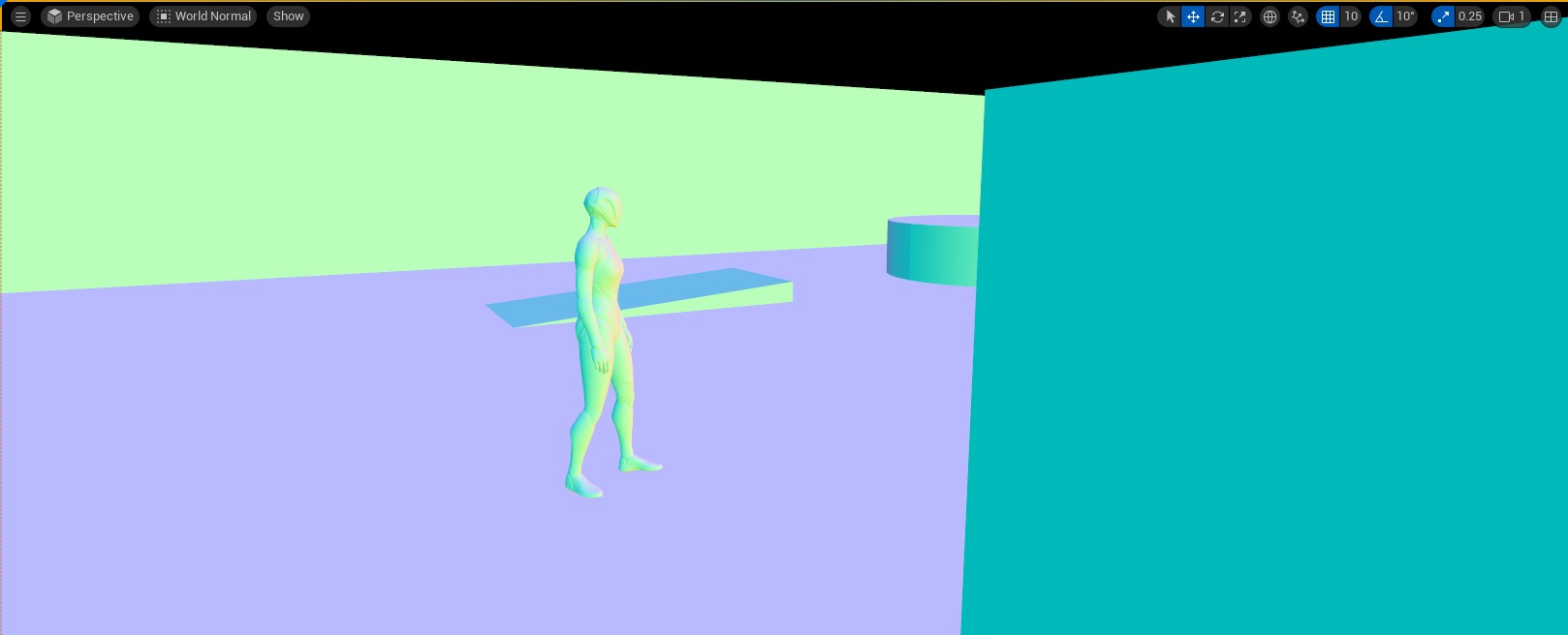
Visualising Normals in Unreal Engine
This view displays the final world-space normal used by the lighting pass for every visible pixel — including normal map contribution. Inverted normals, baking seams, and incorrect imports all show up immediately as wrong colours. It's the fastest way to catch a problem before spending time hunting through material settings.
Key Takeaways
A normal vector is a unit vector perpendicular to a surface. It's the central input to lighting calculations via the dot product, and it also drives backface culling, collision response, and reflection sampling. Getting normals wrong, or using the wrong normals, affects all of those systems.
Normal maps extend this by providing a per-pixel normal rather than a per-vertex one. Each texel encodes a direction vector packed into RGB, allowing the GPU to evaluate lighting as if the surface had far more geometric detail than it actually does. Tangent space is the default because it's portable, tileable, and compatible with animation — the characteristic blue colour comes from the flat reference direction (0, 0, 1) in that local coordinate frame.
The most common production problems — the DirectX/OpenGL Y-flip, incorrect sRGB import, and tangent basis mismatches — all have straightforward fixes once you understand what the map is actually storing and where the conventions differ.
Further Reading
- Normal Map Technical Details (Polycount Wiki)
- Normal Mapping Overview (Wikipedia)
- Mikktspace — the tangent space standard
Found this useful? Share it: